- For Modbus command frame configuration, refer the table. You can add new modbus request string via the edit section.
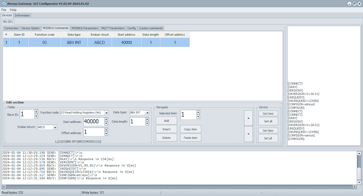
| Field | Value | Description |
|---|---|---|
| Slave ID | Integer[1...255] | Slave ID |
| Function code | Read Coils(1) | Read Discrete Input(2) | Read Holding Register(3) | Read Input Register(4) | Specifies the type of register being addressed by a Modbus request |
| Data structure | 8bit INT | 8bit UINT | 8bit HEX| 16bit INT |16bit UINT | 32bit float | 16bit HEX | 32bit HEX | Bool | Defines how read data will be stored |
| Start address | Integer [0 – 65535] | First Modbus register from which data will be read |
| Offset address | Integer | The starting address or position of a data element within a register or data block |
| Data length | Integer [1 – 30] | Number of Modbus registers that will be read during the request |
| Endian structure |
32bit data – ABCD | BADC | CDAB | DCBA 16bit data - AB | BA |
Select endian structure of data type |
| Trigger | - | Not available now |
| Triggering time | - | Not available now |
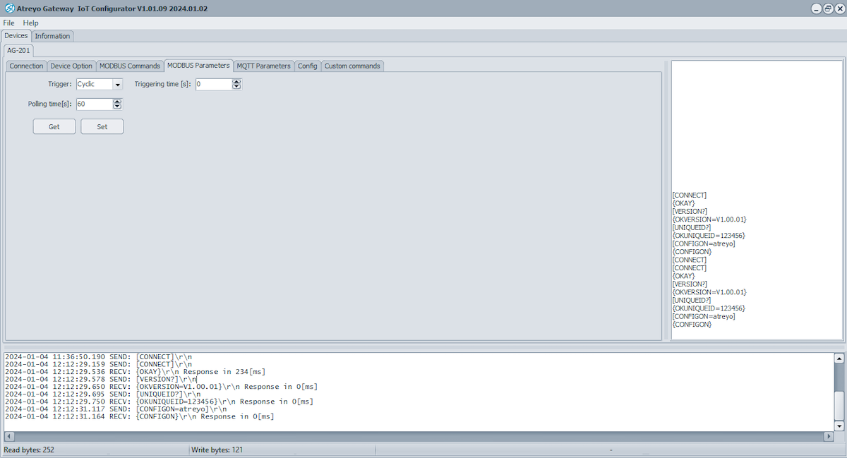
| Polling time | integer [1..]in sec; default: 60Sec | Interval at which requests are sent to the server device. |
- By clicking ADD, you can add multiple Modbus request strings.
- Click "Set" to save a single frame or "Set All" to save all the Modbus request strings in the device.
- clicking "Get" or "Get All", to access the saved Modbus strings in the device.
- Additionally, you can delete, copy, and paste strings from the Navigate section.
- Go to Modbus parameter section and set polling time of modbus data to the server by click on "Set". Also check polling time from device by click on "Get"